


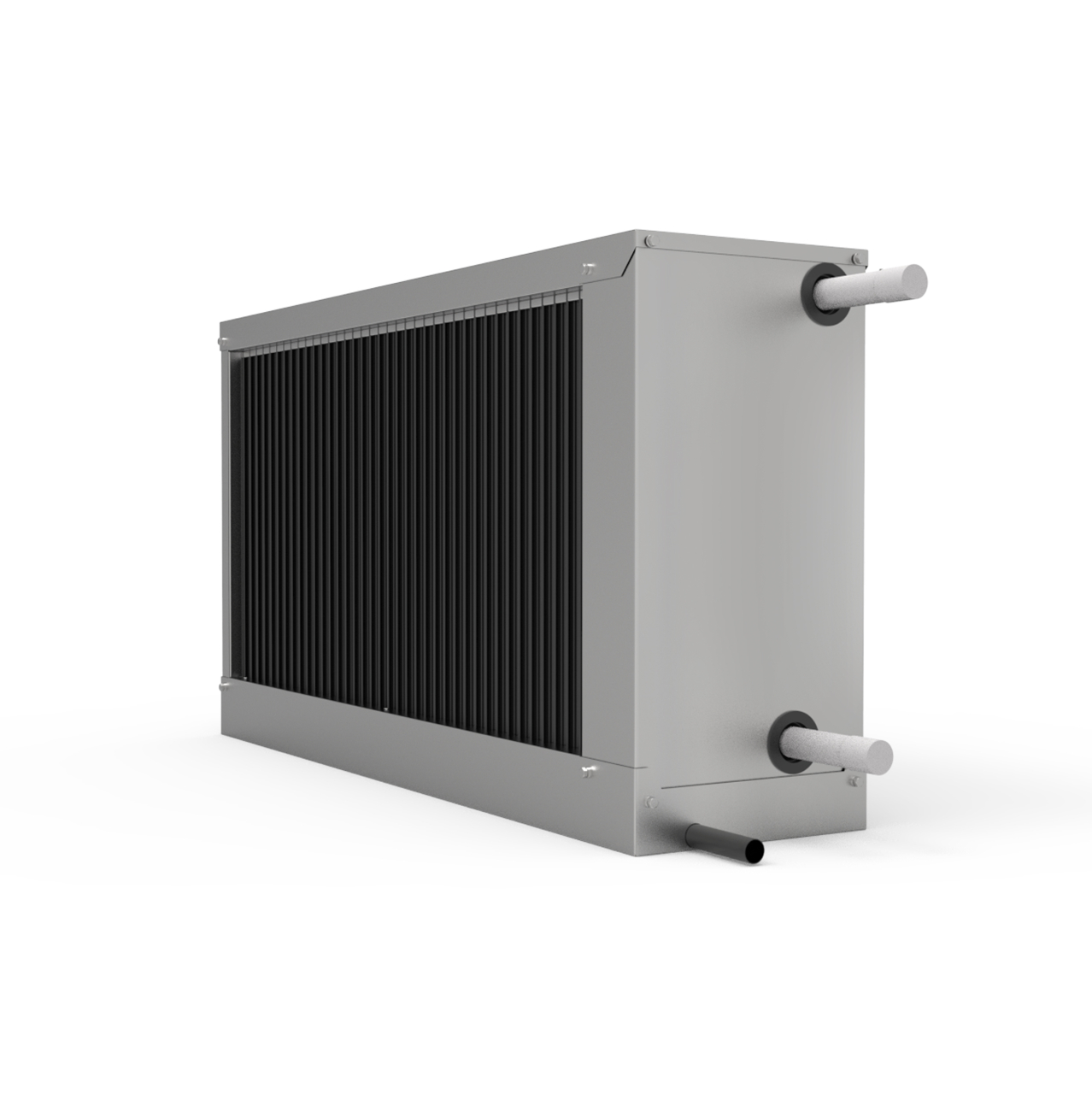
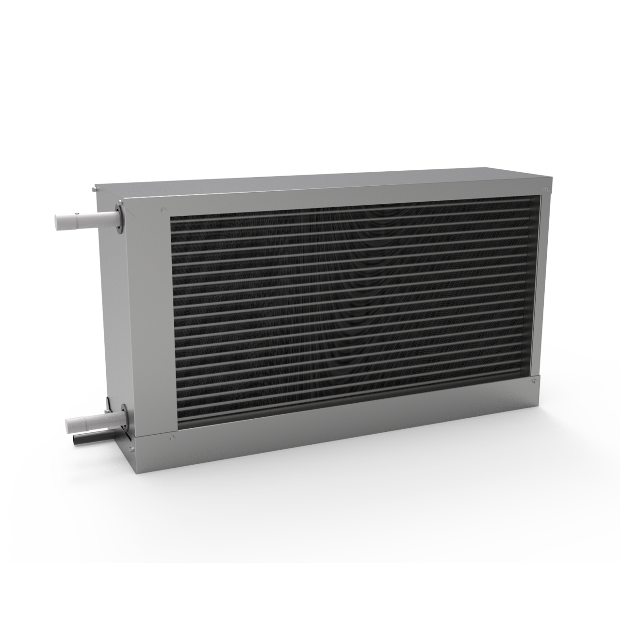
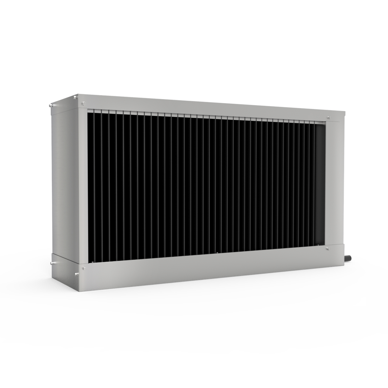
FEATURES
SWH design
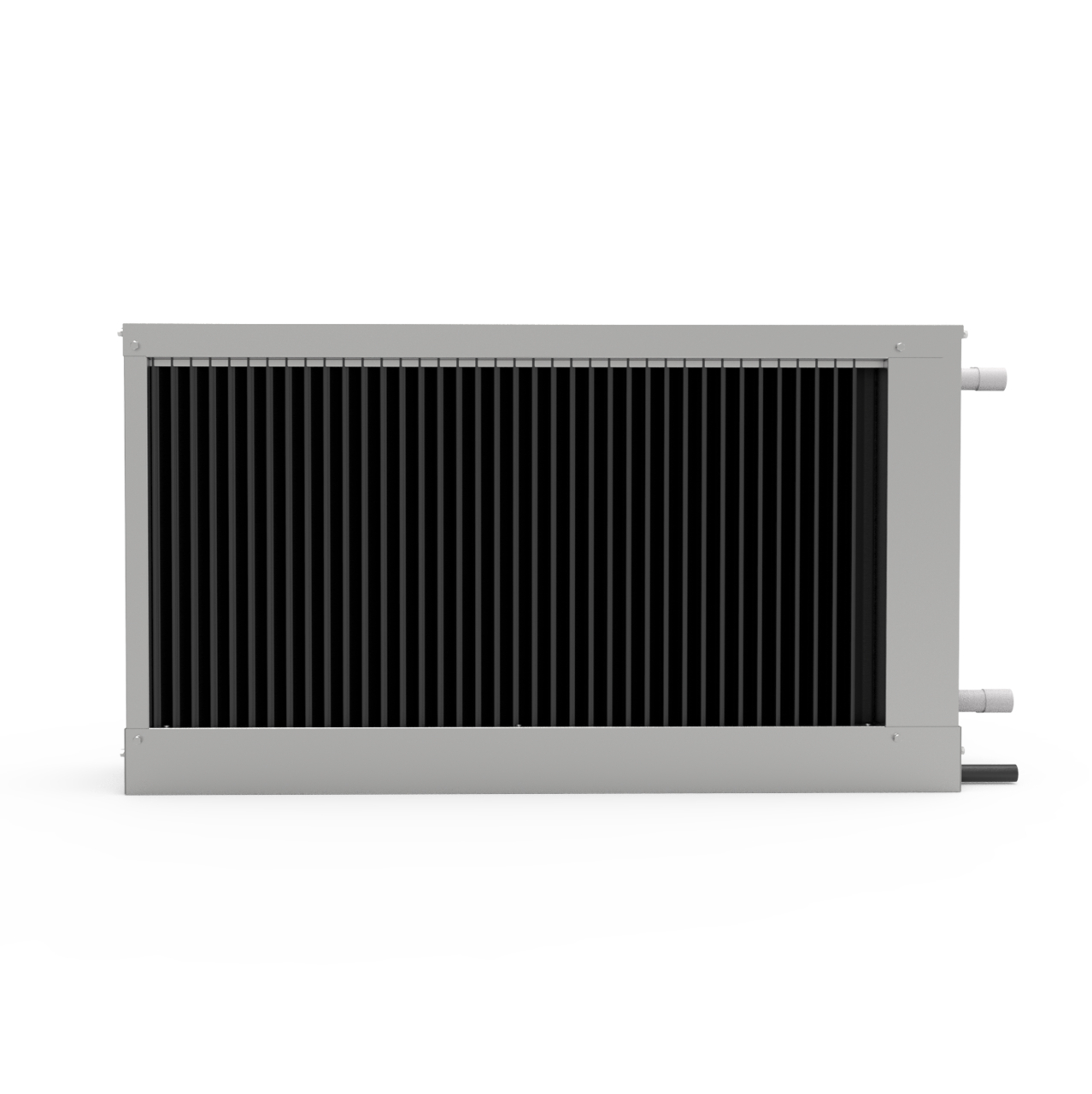
The cooler body is made of galvanized steel. The collectors are welded from steel tubes with a surface treatment with synthetic paint. The heat exchange surface is created by 0.1 mm thick aluminum plates strung on copper tubes.
The condensate collection tray is made of painted galvanized steel or stainless steel. The coolers are tested for air tightness under a pressure of 2 MPa for 5 minutes under water.
The coolers are supplied as standard in a left-hand version when viewed in the direction of the air flow, and are also equipped with a drip catcher and an insulated tub for condensate drainage.
In the case of two-stage cooling, it is advisable to turn off the drip catcher in the first cooler (order the cooler without a drip catcher).
When installing the cooler on the drain pipe, a siphon must be installed, which is calculated by the formula:
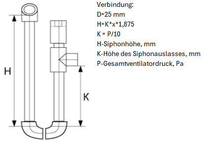
Operating conditions:
Maximum allowable pressure 1.5 MPa
The nomograms indicate the parameters of the chillers for standard values of water temperature difference, different air flow rates and different air temperatures for water used as a refrigerant.
Installation location:
When choosing a location in the ventilation equipment, it is recommended to adhere to the following rules: if the refrigerant is water, the coolers can be installed inside heated rooms in which the temperature does not drop below zero (the main condition is to maintain the temperature of the transported air).
Outdoor installation is allowed if the refrigerant is a non-freezing mixture (ethylene glycol solution). In this case, the temperature limit for the mixing unit servo drive must be taken into account, and the specified diagrams can be used to determine the cooler parameters.
The coolers can only be operated in a vertical position, which allows condensate to be drained and the cooler to be vented. It is necessary to provide control and service access to the cooler. An air filter must be installed in front of the cooler to protect it from contamination (if it is not present in front of the heater). To achieve maximum cooling capacity, the cooler must be connected countercurrently.
The cooler can be installed in front of and behind the fan. If the cooler is installed behind the fan, it is recommended to provide a section between them to stabilize the air flow.