Purpose
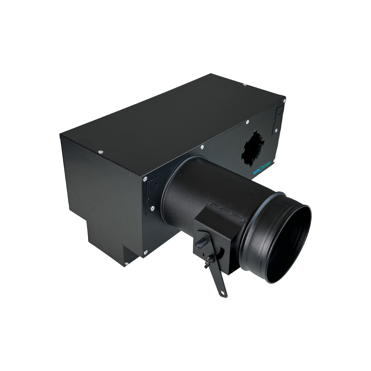
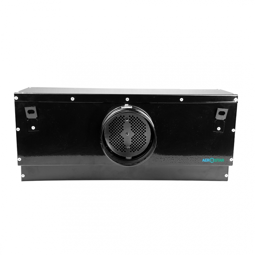
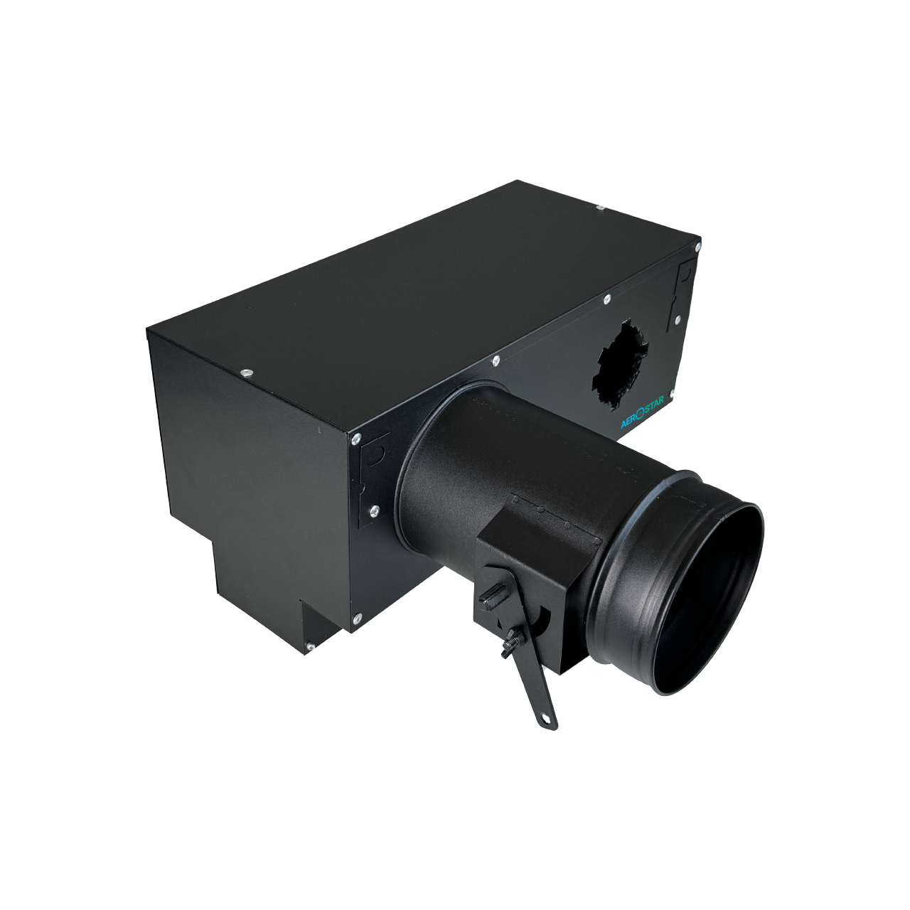
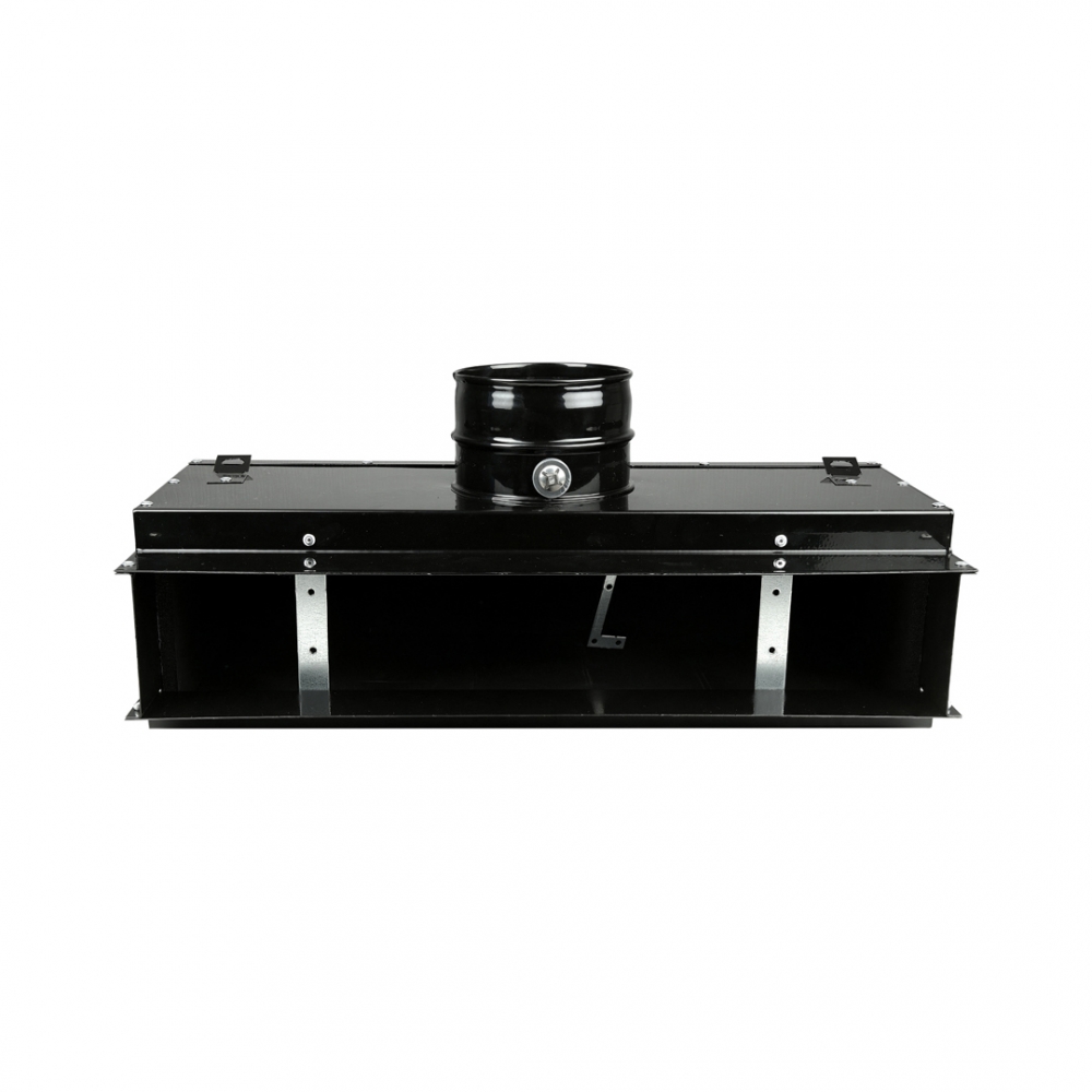
Plenums are designed to connect air distribution devices (slot diffusers and grilles) to the air duct system in supply and exhaust ventilation or air heating.
Construction and materials
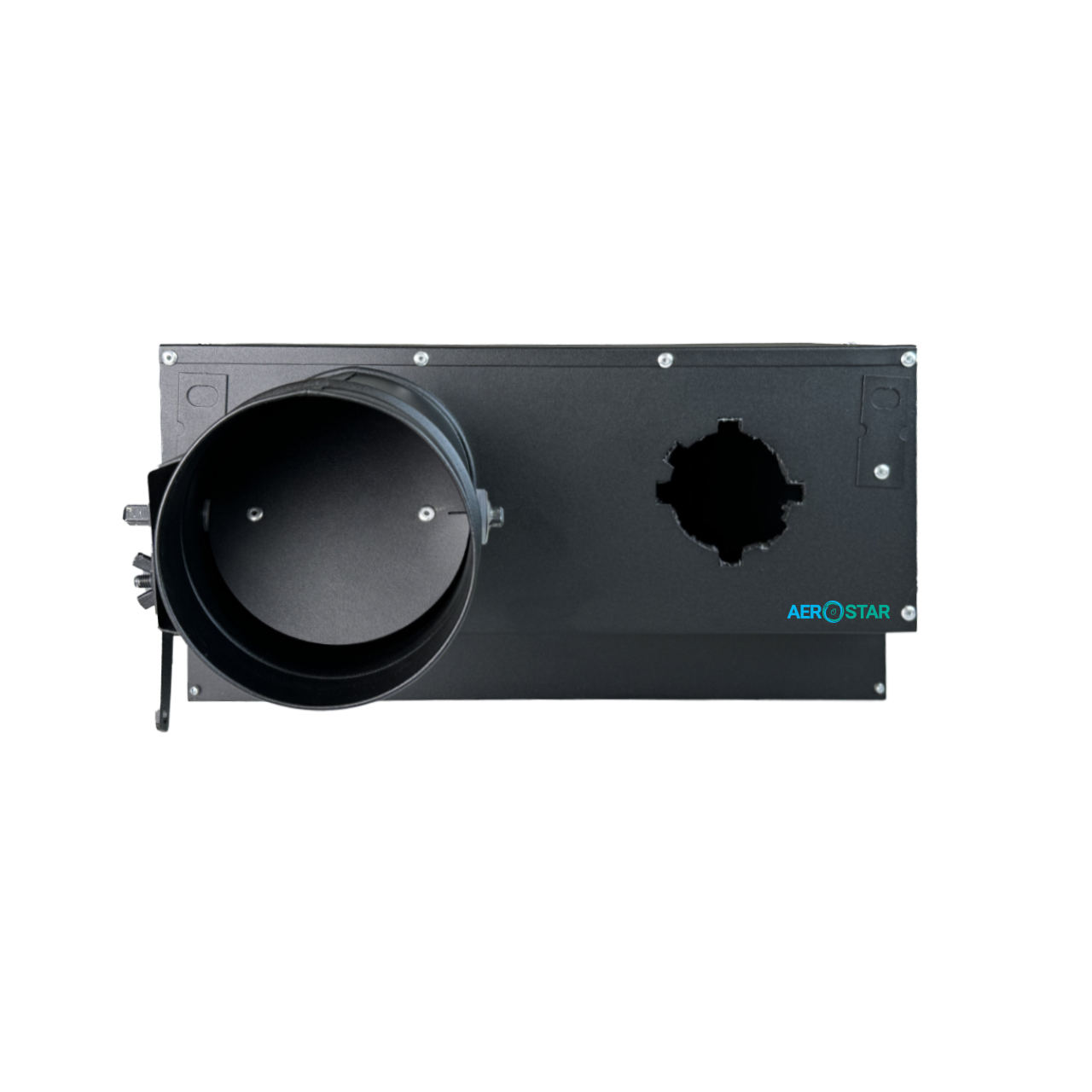
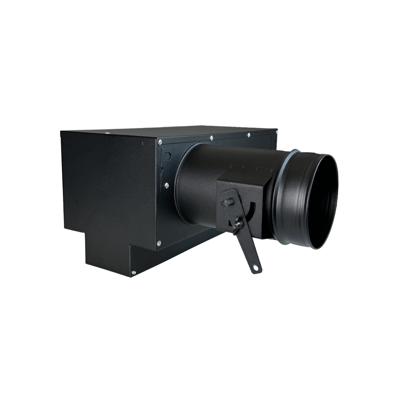
Made from galvanized steel. Connection can be either side or top.
The inlet pipe is made for a nipple connection with an outer diameter of -3 mm from the nominal one.
They have a “correct” shape with a mixing chamber to reduce the flow rate and more even distribution along the entire length. Planks with holes and cut threads for screw connection of slot diffusers with them are pre-installed. The maximum length is 2m, you can dial them in one endless line, while the first plenum will not have a right end cap, the second and subsequent ones will not have end caps on both sides, and the last one will not have a cap only on the left side. To connect them to each other, a connecting bar with holes is additionally installed on one of the plenums, where there is no plug, and on the second, attached to the first, holes are made in advance and they are assembled by laying the plenum on the bar, aligning the holes on the plenum and the bar, and then connect them between each other using rivets or screws.
For lengths over 1200 mm, we recommend installing two or more tie-ins for more uniform air supply along the entire length of the diffuser.
Additionally, it can be equipped with:
– a throttle valve for adjusting the supply air volume;
– adjustable shutter from the inside (the blade is perforated, the adjustment knob is displayed inside the plenum);
– insulation inside the plenum to reduce noise flows;
– flanging around the perimeter;
– powder painting inside/outside according to the RAL catalogue.
Production
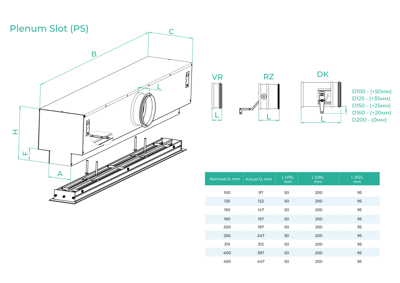
According to the mounting dimensions АxВ (there should always be a gap of 2-5 mm between the mounting dimensions of the diffuser and the dimensions of the plenum connection), the height H should not be less than d+F (standard 50 mm, not less) + 30 (with side connection). N-r: if the insert is d125, then the minimum height H will be 205 mm (50+125+30). If the connection is upper, then the height can be at least 150 mm (F50+100).
An example of ordering and installation
Plenum slot PS-G=500 170x1505/C=270/F=40/H=170h/LC/Izol/RZ d-100 (RAL 9005M/RAL 9005M)
PS - plenum slot closed at both ends (when several elements need to be assembled in a single line, the first left PS-L, PS-C - central, PS-R - right);
-G=500 - this is the distance to the partition in the middle of the plenum from the left edge for separating ventilation and air conditioning flows
170 - plenum connection width (+2-3 mm for the width of the dense diffuser)
1505 - plenum slot length (+5 mm to the length of the dense diffuser
C=270 - chamber width (standard A+100 mm);
F=40 - mounting height of the dense diffuser (not less than the height of the dense diffuser);
H=170h - total plenum height (calculated using the formula: F+d connection+20);
LC - side connection (TC - top connection);
Izol - sound insulation in the middle of the plenum;
RZ d-100 - adjustable damper from the middle of the plenum;
(RAL 9005M/RAL 9005M) - painted black from the middle and outside
In order to facilitate the installation of plenums to building structures, there are fastening plates on the side faces.
Complete set
It is possible to complete with additional elements (options):
- a throttle valve instead of a cut-in;
- adjustable damper;
- powder painting;
- insulation;
- selection.